
Hydraulic booster
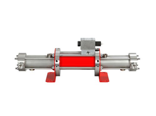
Gas booster hydraulic cylinder
We have developed the heart of the compressor machine which is driven by the hydraulic booster for attending high pressure, which enables high boosting applications .The developed equipment is a two / three stages hydraulic gas compressor, with suction pressure that can vary between 40 and 180 bar and discharge flow pressure between 100 and 350 bar.
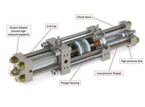
Inside the cylinder , there are pistons in each stage which reciprocates . The mechanical actuation is through a hydraulic pump driven by electric motor. The gas coming from the network,
it’s filtered, and then sucked into the chamber of the 1st stage, through two inputs respectively located at the top and at the bottom of the cylinder, inside of which it’s compressed by the reciprocating movement of the piston. The inlet gas is filtered first to avoid small foreign bodies which can damage the cylinder. The compressed gas exits from the cylinder at the discharge pressure through two outputs (one at the bottom and the other at the top) to enter the first heat exchanger to cool off the gas . The liquid , compressed in the first cylinder, enters the second stage chamber to undergo the second compression.
From the cylinder, after having passed through the second heat exchanger gas , it’s sent to for use at high pressure (200 - 250 bar). In the circuits of the gas, on delivery of both stages, are mounted a pressure switch and a safety valve that will intervene whenever the threshold values of the set pressure is exceeded.
Application suitable as per our manufacturing specifications :
- High pressure storage and transfer
- Auto & lift truck refuelling , CNG gas compressor
- Fuel Cell Research equipments
- Pressure Testing
- Hydrogen filling stations
- Charging high-pressure gas cylinders and receivers
- Hydraulic accumulator charging
- Charging air bag from storage vessels
- High pressure Laser cutting and welding
- Hot isostatic pressing
- Gas assisted plastic injection moulding
Lorem Ipsum is simply dummy text of the printing and typesetting industry. Lorem Ipsum has been the industry's standard dummy text ever since the 1500s, when an unknown printer took a galley of type and scrambled it to make a type specimen book Lorem Ipsum is simply dummy text of the printing and typesetting industry.
Lorem Ipsum has been the industry's standard dummy text ever since the 1500s, when an unknown printer took a galley of type and scrambled it to make a type specimen book Lorem Ipsum is simply dummy text of the printing and typesetting industry. Lorem Ipsum has been the industry's standard dummy text ever since the 1500s, when an unknown printer took a galley of type and scrambled it to make a type specimen book
Lorem Ipsum has been the industry's standard dummy text ever since the 1500s, when an unknown printer took a galley of type and scrambled it to make a type specimen book Lorem Ipsum is simply dummy text of the printing and typesetting industry. Lorem Ipsum has been the industry's standard dummy text ever since the 1500s, when an unknown printer took a galley of type and scrambled it to make a type specimen book
HYDRAULIC WATER / LIQUID INTENSIFIER
We have developed the heart of the compressor machine which is driven by the hydraulic booster for attending high pressure, which enables high boosting applications .The developed equipment is a two / three stages hydraulic liquid compressor, with suction pressure that can vary between 40 and 180 bar and discharge flow pressure between 100 and 350 bar.
Inside the cylinder , there are pistons in each stage which reciprocates . The mechanical actuation is through a hydraulic pump driven by electric motor. The gas coming from the network,
it’s filtered, and then sucked into the chamber of the 1st stage, through two inputs respectively located at the top and at the bottom of the cylinder, inside of which it’s compressed by the reciprocating movement of the piston. The inlet liquid is filtered first to avoid small foreign bodies which can damage the cylinder. The compressed liquid exits from the cylinder at the discharge pressure through two outputs (one at the bottom and the other at the top) to enter the first heat exchanger to cool off the liquid . The liquid , compressed in the first cylinder, enters the second stage chamber to undergo the second compression.
From the cylinder, after having passed through the second heat exchanger liquid, it’s sent to for use at high pressure (200 - 250 bar). In the circuits of the liquid, on delivery of both stages, are mounted a pressure switch and a safety valve that will intervene whenever the threshold values of the set pressure is exceeded


